

-= Metric Halo MIO 2D +DSP =-
.:: MH 2882, ULN2, & ULN8 ::.
Tips, Tricks, and Tweaks
---------------------------------------------------------
These instructions are translated from the German MH Shop at the ULN8 launch.
Current instructions are located at MH Labs
--------------[ULN8 Front Panel Controls]--------------
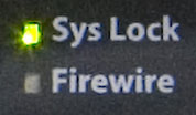
-- System Lock --
The "FireWire" status LED glows green when the device is a valid sequence of isochronous cycles on the connected FireWire connection and recognize that a two-way communication with the FireWire bus is taking place.
The "The Sys Lock" status LED glows green when the internal clock (PLL) is synchronized and parameters within the normal working area, in other words, the device works with a valid source for the synchronization of the sample rate.
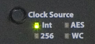
-- Clock Source --
Clock Source is selectable from the front panel clock control. It can be changed from Internal, AES/EBU Sync, Word Clock, or 256x Super Clock.
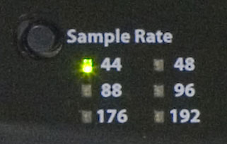
-- Sample Rate --
When the Clock Source is set to Internal, you can also change the sample rate directly from the panel. (when the unit is slaved to external clock, it uses that master clock rate)
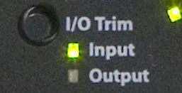
-- I/O Trim --
The I/O Trim allows the user to use the 8 rotory knobs to change either input or output trim.
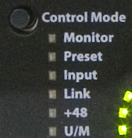
-- Control Mode --
The ULN 8 offers a new feature for MIO devices which is labeled Control Mode. The Control Mode options are limited by the Input or Output mode. (ex: +48v cannot be applied to outputs) However functions like Link are able to be performed in both directions.
Monitor Mode
If the monitor mode is selected, the eight buttons of the channel control knobs act a selection switch for the defined monitor controls within the MIO Console Monitor Controller. This requires that the ULN-8 is connected to a computer with the MIO Console running. I/O Control section is used to change the Monitor routing by allowing the selection of sources and destinations from the front panel by selecting either Inputs or Outputs before selecting the Monitor Mode.
The currently selected monitor (source or destination) is represented by a bright yellow LED ring around the channel button shown.
The communication between the Monitor Controller in the MIO Console and the control panel is bidirectional, so that changes to the computer from the control panel immediately displayed, and vice versa.
Preset Mode
"Preset" is a selection of save-state equipment configurations, with the help of the eight-channel knobs these save-states are retrieved from the device's internal flash memory in the hardware and are loaded as the current running state. If the preset mode is selected, the channels light up according to the preset number and the corresponding LED light rings. Pressing a green light knob loads the saved configuration and the color of the LED ring will change to yellow, which denotes the currently loaded snapshot.
Input
If "input" in the input mode is selected, the button toggles the knob on the input mode between line input, microphone input and send / return mode.
Channel Link
If "link" is selected, the control knobs control which channels are linked. The system of coupled level controls on the ULN-8 control panel is very flexible and enables various coupling of input channels as well as the coupling of different output channels.
Pairing types: The basic principle of the channel coupling is that a main (first) channel is selected, then the other channels will be connected and slave to it. Now when the main channel changes the linked channel will follow. The linking takes place only in one direction: Changes made to one of the paired channels will not reflect on the main channel. This allows for submixing across the front panel for example.
When link is first enabled , all the status LEDs are blank. The main channel is selected by pressing the knob for the selected channel. This lights it up green. Then, the channels to be connected to the main channel are assigned by pressing the knob. These glow yellow. To create a new linking, the button on the current green-lit main channel is pressed to reset, whereupon all status LEDs are extinguished. Now, by pressing a new knob, a new main channel can be determined, and additional channels linked to it.
for a channel pair, (ex 1+2) with both sides controlling level, proceed as follows:
1) "link" to select link mode
2.) knob 1 press to define it as the main channel to control - a green ring lights
3.) knob 2 Press to link it to channel 1 as a pair - yellow ring lights
4.) knob press 1, to reset the selection - no ring lights
5.) knob 2 Press to define it as the main channel to control - a green ring lights
6.) knob press 1 to link it to Channel 2 as a pair - yellow ring lights
7.) knob 2 Press to deselect - no ring lights
After step 4, the unit is mapped so that a rotation of knob 1 changes the level of channel 1 and 2, but not vice versa. After step 7, both knobs in both directions are linked, so that any rotation in one of the knobs reflects on both channels.
48V Phatom Power
in I/O Mode the 'Input' must be selected, then each knob press will enable phantom power on that channel. Phantom is able to be enabled on a mic channel, even when in the Line Input view.
Input Trim
The eight knobs each control the level of either the Mic Inputs or Line inputs depending on which is selected. In addition, the numeric value being changed shows on the "output" level meters on the right side of the panel as a bit matrix display.
Each detented knob changes the volume on the selected channel by 1.0 dB. If the knob is pressed, the level value changes in smaller increments of 0.5 dB.
Level changes are automatically applied to all groups and across linked channel that you have configured so that up to eight channels at the same time can be changed.
U/M stands for user mode, and will be addressed in a future software update
-- Mic / Line Selector --
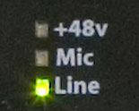
Each channel has it's own Mic / Line selector. These are multi-purpose LEDs are thier response showes different states of the System. The +48 glows red when phantom power is enabled on a mic. The Mic LED illuminates green when a Mic is connected, there are also blinking patterns for Line input, and Send / Return mode.
-- Input Mode --
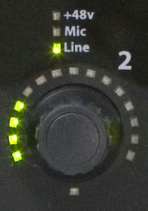
The eight numbered channel rotories are detent encoders with integrated push-buttons. For each knob a set of 15 bi-color LEDs (red / green) are displayed, as well as a two-colored "Flexi LED" below. Both the LED ring and the "Flexi-LED display can be used for different purposes, depending on the setting.
( Ex. if +48v is selected in the Control Mode section, each knob press turns on or off the phantom on that channel.)
Likewise if Input mode is selected in the I/O section, and Mic is selected in the Mic / Line Selector section, and Input Mode is selected in the Control Mode section, the rotoary knobs will change the Input Level, the meter level section will also display on the knob LEDs
-- Meters --
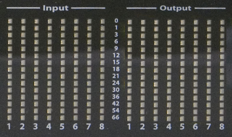
Each segment in the meter is a two-color LED, you can color using the software. The level meters are preset so that the Green to -12 dBFS, to -1 dBFS is yellow and red at 0 dBFS are displayed. These thresholds are user definable. If the clipping value for a particular channel is exceeded, the color changes the meter fully to red and stays for the specified time interval at this color. This feature alerts you immediately at every level exceeded.
The default for the output level meters is an overload value of 0 dBFS so that the entire meter glowing overload warning is not enabled. This default was chosen because when playing current day high level over-compressed tracks, the clipping warning would almost always trigger.
-- Output Meters --
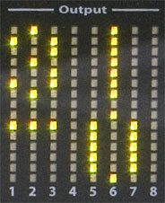
The output level display offers an additional feature. If a value for one of the inputs or outputs, or a monitor-level change, the output level display will show the number value in dB for a short time, where the LEDs act as a dot-matrix. The digits are arranged in two rows, the upper row shows the integer values, the lower shows the number sign and the first decimal place. A positive gain chainge appear green, a negative change turns the LEDs yellow numbers. (ie. 31.0 dB in this example)
-- AES Status --
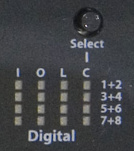
The AES status indication consists of a total of 16 LEDs, divided into four columns and four rows. Each row represents a different AES or cable connection, each connection has two channels of audio transports. Accordingly, the columns are named, ie 1 +2, 3 +4, 5 +6 and 7 +8. The columns include four different status information:
I - Input - level for each connection, dimming LEDs
O - Output - level for each connection, dimming LEDs
L - Lock - sync input for each connection
C - Clock - AES input as clock source
The LED for the input and output level shows the highest value on the corresponding channel pair basis of brightness and color. The Select button selects which channel pair is carrying the Master Clock sync when the unit is clocked externaly over AES.
-- Monitor Control --
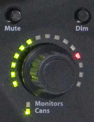
The monitor control features allows both the level of the headphone output as well as the level of the main monitor outputs to be adjusted. Pressing the knob as a button toggles between the two destinations. The current output is shown on the status LED below the monitor control knob.
Above the Monitor control are two buttons, "Mute" and "Dim", which act as switches and apply to the currently selected monitor destination (either mains or cans). If the "Mute" button is pressed, it changes the status LED for the monitor to "red" and the output is muted. If the "Dim" button pressed, it changes the status LED for the monitor to "yellow" and the output level will be lowered by 20 dB. "Mute" and "Dim" can be activated simultaneously, with "Mute" any time overriding and muting output.
If the "Mute" and "Dim" buttons simultaneously pressed, a mute all inputs and outputs is activated to ensure quick response in case of clipping or possible feedback.
This panel contains a separate headphone output with its own DA converters, headphone amplifiers and analog volume control. By default this controls the 'Cans' volume.
---------------===[
Thanks ]===-----------------
All this content came from somewhere, mostly ctrl C . The community at
large is to be thanked ... but I would like to extend particular thanks
to BJ, Jon Stern, Allen Rowand, Steve Meyer, Brian Peters, Sean Witters, Mike Raznick, Hiro Honshuku, Geert Bevin, the beta crew, devs,
and ALL the Contrib
Main
- Metric Halo Online
- Metric Halo FAQ
- MH Technotes
- MH V5 Movies
- MIO Downloads
- MH Registration
- MH Support Ticket
- FOO Mailing List
- MIO Mailing List
MIO Resources
- Big Blue Lounge/ OSX
- GearSlutz MH News
- Gearslutz ULN8 News
- Spectrafoo Mix tutorial
- MIOs for adoption
- SOS Legacy +DSP
- A-NO-NE MH
- Spectrafoo Manual
- +DSP Manual
- Channel Strip Manual
- 2882 Manual
- ULN2 Manual
MIO IPod Movies
- Teaser Trailer
- Mixer Overview
- Mixer Config
- Manual Mix Config
- Templates
- FW Routing
- Monitor Controller
- Hardware Remap
- Foo ITunes
- Foo Sends
- Foo Tutorial 1
- Foo Tutorial 2
- Foo Tutorial 3
- FW Console Connect
- Legacy Box Config
- Mainstage
- MC Shuttle
- Multibox Routing
- Simple Input
- Simple Output
- Surround
- V5 Record Panel
- MIO Logic Automation
- 2882 Disassembly
- ULN2 Disassembly
MIO Tech Notes
- Foo Multizone Xfer
- Foo FW routing
- Foo & XTA tuning
- Foo Xfer balc tuning
- Foo weight EQ
- Foo SPL & flowchart
- Legacy Routing
- Logic Mono Bussing
- MIO Automation in DP
- MIO + Bidule
- MIO in Windows
- +DSP Program Duck
- +DSP BassRekker
- +DSP RingMod LFO
- +DSP Chorus
- +DSP Stereo Leslie
- Channel Strip SSL v1
- Channel Strip SSL v2
MIO Navigation
- MIO Disassembly
- MIO Inside
- Flash Firmware
- Reset & Service Menu
- Erase Boot-State
- Network Remote
- System Log
- Screen Shots
- Key Bindings
- Mobile IO Clock
- Mobile IO Converters
- MIO Analog Stage
- MIO Mic Gain
- MIO Mic Sensitivity
- Power Consumption
- Min/Max Specs
- +DSP Latency
- 2D Character
- +DSP EQ
- ULN8 DB25 Pinout
- ULN8 Input Specs
- ULN8 Input Diagram
- MIO Video Sync
- MIO Logic Automation
- MIO Cubase Automate
- MIO XYtri 7.1->stereo
- ULN8 Front Panel
- CS vs MIO Strip
- Rec Panel Interleave
IRC
irc.EFnet.org
#osxaudio
 +2D
+2D| Character (22 types) |
| MultiBus V5 Mixer |
| Surround Support |
| Monitor Controller |
| HaloVerb |
| Bass Head |
| Bass Head Shape 1 |
| Bass Head Shape 2 |
| British Mil Spec |
| British Mil Spec Bright Cab |
| British Mil Spec Grind |
| British Mil Spec Light Grind |
| British Mil Spec Rhythm |
| British Mil Spec+Vibrato+Trem |
| MH Clean |
| MH Clean Tweed |
| MH Hi-Gain |
| Small Dark |
| Small Dark No Cab |
| Small Tweed Crunch |
| Small Tweed Touch O' Dirt |
| Autoflanger |
| Autoflanger 2 |
| Autoflanger 3 |
| Cool Mono Echo |
| LoFi Mod Echo |
| Mono Rotary |
| Slap Delay |
| Vibrato+Tremolo |
| Stereo Rotary Speaker |
| Diffuse Prime |
| Diffuse Room |
| Early Diffuse Room (no tail) |
| Hall 1 |
| LongVerb |
| Med Diffuse Room |
| ModVerb |
| Small Diffuse Room |
| Parallel Compressor |
| Parallel Limiter |
| Mid-Side Compressor |
| Mid-Side EQ |
| Mid-Side Limit |
| Stereo Parallel Limiter |
| Nezumi |
| Nezumi Less Gain |
| Screamer |
| Closed 2x12 |
| Closed 2x12 with Air |
| 4x12 Cab |
DSP explained
DSP Math
| ABS |
| Max |
| Min |
| Select |
| Map Range |
| Constant |
| Divide |
| Square Root |
| Reciprocal Square Root |
| ADSR |
| Exponential ADSR |
| Band Split |
+DSP Graphs
2D Character